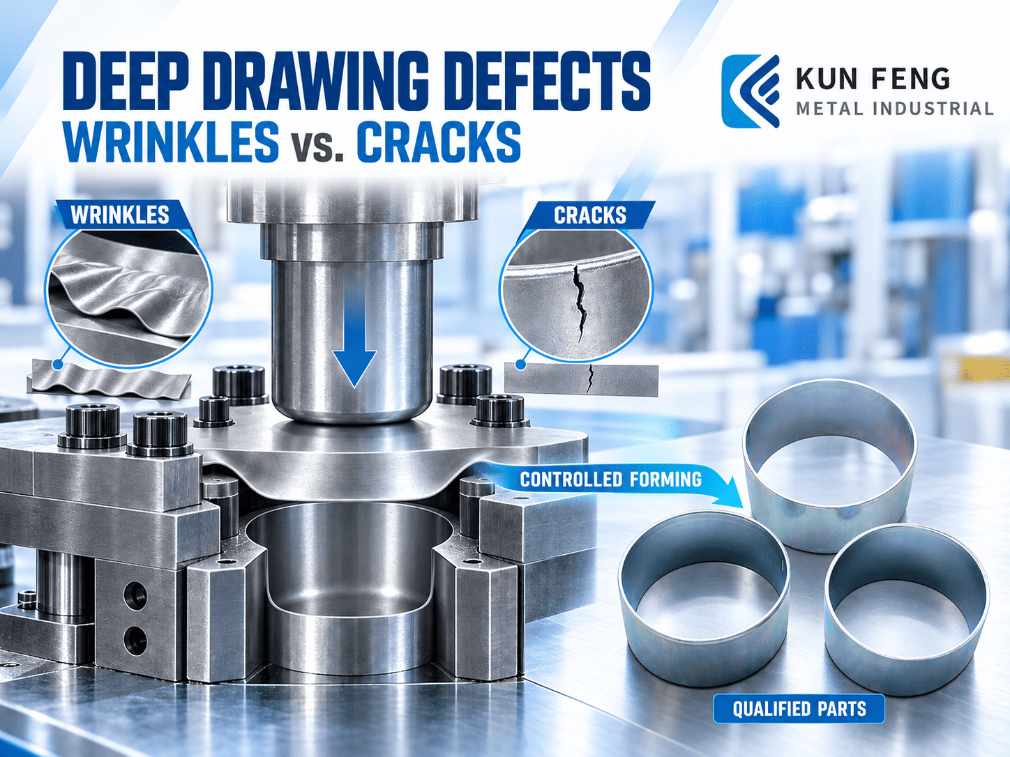
Deep drawing uses a punch and die to transform a flat sheet-metal blank into a cup-shaped, box-shaped, or other three-dimensional component. During forming, the material must flow into the die at a controlled rate. If this flow becomes unstable, wrinkles may develop; if the sheet is stretched beyond its forming capacity, thinning and cracks may occur.
These defects are rarely caused by one setting alone. Material properties, sheet thickness, part geometry, tooling radii, clearance, blank holder force, lubrication, and the number of forming stages all affect the result.
At KUN FENG METAL INDUSTRIAL CO., LTD., we consider these factors during tooling development and production planning. Our objective is not simply to produce one acceptable sample, but to establish repeatable forming conditions for volume sheet metal stamping.
1. Why Do Wrinkles and Cracks Occur in Deep Drawing?
During deep drawing, the punch draws the blank into the die while material from the flange moves inward. The flange is subjected to radial tensile stress and circumferential compressive stress as the material flows toward the die cavity. The circumferential compressive stress can cause the flange to buckle and form wrinkles, while tensile stress in the wall and radius areas can contribute to thinning and cracking.
Wrinkling generally occurs when compressive stress causes an insufficiently restrained area of the sheet to buckle. It commonly starts in the flange and may be carried into the wall as forming continues.
Cracking occurs when tensile strain becomes concentrated in a local area and exceeds the material’s forming capacity. Common risk areas include the punch radius, die radius, sidewall transitions, and the corners of box-shaped parts.
Wrinkling and cracking are therefore two different results of uncontrolled material flow. Increasing the blank holder force may suppress wrinkles, but excessive restraint can also increase thinning and fracture risk.
| Condition | Wrinkling | Cracking |
|---|---|---|
| Basic mechanism | Buckling under compressive stress | Failure under excessive tensile strain |
| Common locations | Flange, upper wall, transitions | Punch radius, sidewall, corners |
| Typical concern | Material enters the die too freely or unevenly | Material flow is too restricted or strain is too concentrated |
| Engineering objective | Stabilize inward material flow | Reduce localized stretching and thinning |
Key Takeaways
- Wrinkling is generally related to circumferential compressive stress and unstable material flow.
- Cracking is generally related to excessive tensile strain or localized thinning.
- The complete forming process should be reviewed before changing an individual setting.
2. How Material Formability and Sheet Thickness Affect the Result
A material should not be selected for deep drawing based only on its general alloy family or nominal strength. The exact grade and mechanical properties affect how much deformation the sheet can withstand before necking, splitting, or becoming unstable.
Important characteristics include ductility, yield behavior, tensile strength, work-hardening response, and plastic anisotropy. Rolled sheet metal may not deform equally in every direction. This directional behavior can contribute to uneven rim height, commonly known as earing, and may also affect material distribution around the part.
Sheet thickness also influences forming performance. A thinner sheet is generally more sensitive to buckling and localized thinning. For the same material and comparable geometry, a thicker sheet generally requires greater forming force and corresponding tooling capacity. Variations within the specified thickness tolerance may also change friction, clearance, and material flow during production.
KUN FENG’s general stamping capabilities support commonly used materials such as carbon steel, stainless steel, aluminum, copper, and copper alloys. However, this does not mean every grade or thickness is automatically suitable for deep drawing. Feasibility must be evaluated according to the actual material specification, part geometry, and production requirements.
Key Takeaways
- Specify the complete material grade, mechanical requirements, and sheet thickness.
- Consider rolling direction and anisotropy when rim height or appearance is important.
- Confirm feasibility using the actual material planned for production.
External Reference: WorldAutoSteel – Advanced High-Strength Steel Application Guidelines
3. Part Depth, Blank-to-Punch Diameter Ratio, and Forming Stages
Part depth alone does not determine the difficulty of deep drawing. Engineers must also consider the part diameter or width, starting blank size, material properties, sheet thickness, corner geometry, and the amount of material that must flow into the die.
For a cylindrical cup, the blank-to-punch diameter ratio is commonly expressed as:
A higher blank-to-punch diameter ratio generally indicates a more demanding draw. However, it should not be treated as a universal pass-or-fail value because the practical forming limit also depends on material grade, thickness, tooling radii, friction, blank holder conditions, and process control.
Box-shaped and irregular components require additional attention. Unlike a round cup, material does not flow uniformly around their perimeter. Straight walls, corners, and transitions experience different strain paths, which can create localized areas of wrinkling or cracking.
If the required shape cannot be formed reliably in one operation, multiple drawing or redrawing stages may be necessary. Dividing the deformation across several stages can improve material distribution and reduce the strain imposed during any single operation. Trimming, restriking, or dimensional calibration may also be added when required by the final geometry.
At KUN FENG, we evaluate tooling concepts and process sequences according to the part structure, material behavior, production volume, and quality requirements. Drawing operations may be incorporated into an appropriate single-operation, transfer, progressive, or combined manufacturing process, depending on the project.
Key Takeaways
- Evaluate part depth together with the blank size and part dimensions.
- Irregular and box-shaped parts require careful control of nonuniform material flow.
- Severe geometries may require multiple forming stages rather than one deep draw.
External Reference: NIST – Two-Stage Forming: Experimental and FE Analysis
4. Punch Radius, Die Radius, and Tool Clearance
The sheet bends and unbends as it passes over the tooling during deep drawing. The punch radius, die radius, and clearance therefore have a direct influence on forming force, material flow, thinning, and surface quality.
The die-entry radius controls how the material moves from the flange into the cavity. If this radius is too small, resistance increases as the sheet changes direction, which may raise forming force and increase the risk of surface damage, localized thinning, or fracture.
The punch radius influences how strain is distributed between the bottom and wall of the component. A sharp punch radius can concentrate strain within a small area, increasing the likelihood of thinning and cracking. However, an excessively large radius may conflict with the required geometry or reduce control over material flow.
Tool clearance should match the material thickness and forming sequence. Insufficient clearance can restrict material movement and increase friction. Excessive clearance may reduce dimensional control or contribute to an unstable wall condition.
Tool condition should also be monitored during production. Wear, surface damage, contamination, or misalignment can change friction and material flow even if the original tooling design was appropriate.
Key Takeaways
- Evaluate the punch radius and die radius separately.
- Match tooling clearance to the material thickness and forming requirements.
- Include tool wear, alignment, and surface condition when investigating recurring defects.
5. Blank Holder Force and Lubrication Conditions
The blank holder controls how material moves from the flange into the die. If restraint is insufficient, compressive stress can cause the flange to buckle. If restraint is excessive, the material may not flow inward freely enough, increasing drawing force, thinning, and cracking risk.
Blank holder pressure cannot be evaluated in isolation. The required condition also depends on the contact area, blank shape, material thickness, tooling geometry, draw-bead arrangement, and press system.
Lubrication controls friction at the interfaces between the blank, blank holder, punch, and die. A suitable lubricant can reduce galling, surface damage, and unnecessary forming resistance. It may also help maintain more consistent forming conditions over repeated production cycles.
However, more lubrication is not always better. Excessive or unevenly distributed lubrication may reduce friction in areas where controlled restraint is required, potentially increasing the risk of wrinkling. Insufficient lubrication may create high-friction areas that contribute to scratching, material pickup, thinning, or cracking.
Lubricant selection should also account for material compatibility, finished-surface requirements, cleaning, and downstream operations such as plating, coating, welding, or assembly.
Key Takeaways
- Insufficient blank restraint can increase wrinkling risk.
- Excessive restraint can increase thinning and cracking risk.
- Lubrication must balance forming performance with surface and downstream-process requirements.
External Reference: AHSS Guidelines – Forming Strategies and Solutions
6. What Buyers Should Confirm Before Tool Development
Many deep drawing risks can be identified before tooling is finalized. A finished-part drawing is an important starting point, but it may not contain all the information required to plan a repeatable sheet metal stamping process.
For an initial engineering review, buyers should provide:
- 2D drawings and 3D models
- Complete material grade and applicable standard
- Nominal sheet thickness and permitted thickness variation
- Critical dimensions and tolerances
- Part depth, corner radii, and transition geometry
- Surface areas where thinning, tool marks, or distortion are restricted
- Surface treatment and appearance requirements
- Functional and assembly requirements
- Estimated annual demand and batch quantity
- Inspection or documentation requirements
- Downstream welding, coating, plating, machining, or assembly needs
Not every dimension needs the same level of control. Identifying function-critical dimensions allows the tooling and inspection plan to focus on features that affect fit, sealing, alignment, strength, or assembly.
At KUN FENG, we participate in early engineering planning for OEM stamping projects. Our review considers material characteristics, process sequence, tooling requirements, critical dimensions, production volume, and secondary-process needs.
When necessary, we provide design-for-manufacturability recommendations as part of the manufacturing project. Engineering evaluation and tooling development are integrated into the overall production plan to support a reliable transition from tool tryout to volume production.
Key Takeaways
- Provide material, geometry, tolerance, surface, and volume requirements early.
- Clearly identify dimensions and surfaces that affect the part’s function.
- Review downstream processes before the tooling design is finalized.
7. FAQ: Deep Drawing and Sheet Metal Stamping
What is the difference between wrinkling and cracking in deep drawing?
Wrinkling is generally a buckling problem caused by unstable compressive material flow. Cracking is a tensile failure that occurs when a localized area is stretched beyond the material’s forming capacity. Because their mechanisms differ, the same process adjustment may not correct both defects.
Can increasing blank holder force eliminate wrinkles?
It may help control flange wrinkling, but excessive force can restrict material flow and increase thinning or cracking. Blank holder conditions must be balanced with the material, lubrication, blank geometry, tooling radii, and required drawing depth.
Is a deeper part always more difficult to manufacture?
Not necessarily. Difficulty depends on the relationship between depth and cross-sectional dimensions, as well as material properties, thickness, corner geometry, blank design, and forming sequence. A shallow box with tight corners may be more difficult to form than a deeper round cup with favorable geometry.
Can every deep drawing part be completed in one operation?
No. Some components require multiple drawing or redrawing stages to distribute deformation and maintain controlled material flow. The number of stages should be determined through engineering evaluation and tooling development.
Is more lubrication always better?
No. Lubrication reduces friction, but deep drawing still requires controlled restraint. Excessive, insufficient, or inconsistent lubrication can change material flow and cause quality problems.
What materials can KUN FENG process?
Our general stamping capabilities cover carbon steel, stainless steel, aluminum, copper, and copper alloys. Deep drawing feasibility depends on the specific material grade, thickness, geometry, and production conditions.
What information should I provide for a feasibility review?
Provide the part drawing, material and thickness specifications, critical tolerances, surface requirements, production volume, and downstream-process needs.
Prepare Your Deep Drawing Project for Production
Early review of the drawing, material specification, critical tolerances, surface requirements, and production volume helps identify potential forming risks before the tooling is finalized.
KUN FENG combines tooling development and precision sheet metal stamping to support consistent part quality in volume production.
If you are developing a cup-shaped, box-shaped, or other deep-formed component, send us your drawings and production requirements.
Contact KUN FENG for a Project Evaluation